In this next example we will repeat most of the steps taken in the first example. However, this example will have more constraints.
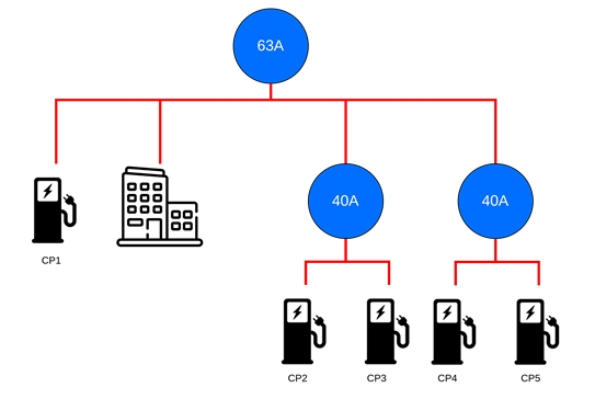
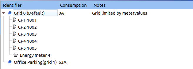
This example has a main fuse of 63A. On this fuse panel is the building and a single charge point. This office building has 2 40A cables which provide power to 2 charge points each. This situation is shown in the next image.
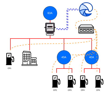
Because we have an uncontrollable load in this grid (the building) there is a need for an energy meter. As stated in “How to configure an enegy meter” the preferred way of using an energy meter is to connect it as close to the fuse panel as possible. There is also the option to use the energy meter to only measure the building’s current. But this is discouraged because you will get more safety when the same energy meter guards the entire grid. Also note that the 2 40A sub-grids don’t need an energy meter because there are no uncontrollable loads in them and the main installation is already guarded. So, when we:
- Connect the stations to edge,
- Finish installing an energy meter and configuring the Energymeter in Edge
- And give the charge points a user-friendly name,
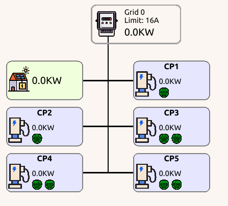
we will end up with the following situation. The left image is the current “live view” without any configuration. The right image is an illustration of a simplified installation we want to configure.
Video Instructions
Grid Configuration
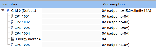
Now everything is installed we can go to the grid-tab in the management interface. As stated before every device is automatically added to grid-0.
We will finish this example with good practice and not utilize grid 0. We will make a new root-grid and start configuring from there.
- Click on “Edit grid”
- Right click BELOW grid-0 on the white space and click on “Add top level grid”. Grid-1 will appear.
- Click on “Grid-1”, change the Grid identifier and set max current to 63A.
- Set the “Max current” from grid-0 to 0A (it was 16A by default).
- Click on the new top-level grid (Grid-1), Change the Panic threshold to 35% (because the appliances in the building can cause surge currents.) and increase the hysteresis range to 10%
- Give Grid 1 an easy recognizable name. e.g. “Office Parking”
- Verify the process with the following image
- Right-click on grid-1
- Click in the sub-menu on “Add grid”.
- Click on the new grid, Set the max current to 40A and optionally change the Grid identifier.
- Repeat the last 2 steps for grid-2 because we need 2 sub-grids in this example.
- Drag CP_1001 and the energy meter in the new root-grid, CP_1002 and CP_1003 in the first Sub-grid and CP_1004 and CP_1005 in the second Sub-grid
- Press “Save changes”
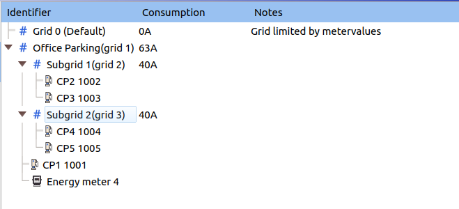
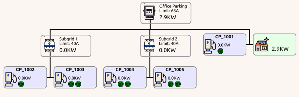
When you go back to the “live view” it should look like this: